THE DEHUMIDIFICATION PROJECT    
  Project operations    
 

Roofs and guttering

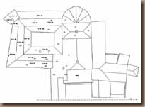
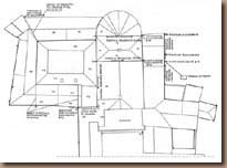
The system of gutters and drain pipes that remove water from the roofs of the building around the cloister has been completely redesigned in the project so as to reduce drastically the volume of water that flows into the cloister. The water is routed towards other parts of the monastery building. Figure 1 shows the plan of the roofing of the whole complex with the present layout of the rain water drainage system. Figure 2 shows the new layout as planned in the project. The roofs and drain pipes have been given numbers. The drainage areas for the various drain pipes have been highlighted.

The plan to modify the rain water drainage system means that some of the piping will have to be routed through the under roof areas in order to carry the water to the opposite side of the perimeter building fabric, instead of flowing into the cloister.

The four roofs covering the corridors will drain directly onto the perimeter paths, which will have a specially designed drainage system (see point two of the project). This will make it possible to eliminate the present system of drain pipes and joints that disfigure the internal walls of the cloister. Under conditions of maximum heavy rainfall, the rain water from this roof area, measuring 220 sq. m., will cause a flow of 0.1 liters/second per linear metro of roof slope (equivalent to half a glass of water for every metro of roof slope) which can easily be handled by the perimeter drains.

The outlets from the wash basins, which at present flow into the south-east and north-west drain pipes in the cloister, will be re-routed to flow into the drainage system used by the wash basins on the other sides of the building.

For a clearer understanding of the project, the table below shows the figures for the surfaces of the various roofs, the capacity in liters per second of the roofs, the new guttering, the drain pipes and piping that passes under the roofs around the cloister (the figures and abbreviations are given on the plans).


Fig. 1 - Roof plan, present state.


Fig. 2 - The Roof: intervention.


Roofs N 1 2 3 4 5 6 7 8,9 10 11 12 13 14,15,16,17 18 19 20 21
Mq 25 64 64 18 18 88 35 100 60 26 24 36 217 25 23 24 45
L/s 0,8 1,8 1,8 0,6 0,6 2,7 1,2 3,3 2 0,8 0,8 1,2 7,2 0,8 0,7 0,8 1,5


In calculating the capacity, we considered the maximum flow in twenty minutes which is 40 mm. in Rome, corresponding to 0.03 liters per second for each square metro.

In carrying out the project, it will be necessary to modify the guttering and drain pipes; all the damaged or broken pieces will substituted with new copper sections.

The following list shows all the actions to be taken for each drain pipe, numbered as in figure 2.

D1 will continue to drain onto roof pitch F8, but will receive water only from the part of the roofing of the apse F1 through guttering.

D2 will have to be substituted and connected to the sewer in Via dei Querceti, Ø 200.

D3 no alteration.

D4 will have to be substituted by one with Ø 160.

D5 new, connected to the gutter which drains into D6, Ø 100.

D6 new, connected to the sewer in Via dei Ss. Quattro, Ø 200.

D7 new, connected to the gutter that drains into D6, Ø 100.

D8 eliminated.

D9 eliminated.

D10 will have to be moved; it receives water from part of the roofing of the transept, which contributes to the flow carried away by D4.


Internal area of cloister

As specified, with regard to the uncovered area of the cloister, once the wash basins and the roof gutters have been removed, it will only be necessary to drain the rain water that falls on the uncovered area, on the four remaining roofs and the waste water from the fountain.

The uncovered area of the cloister has been restructured so as to allow transpiration in the underlying terrain, the conveyance of rain water and water from gardening tasks, and finally transpiration in the base walls of the coupled columns through the construction of a perimeter drainage system that performs the dual function of collecting the water from the overhanging eaves and ventilating the foundation walls and garden soil.

The following operations are foreseen (see the project plan):

  • Stratigraphic excavation of the entire uncovered area of the cloister down to the necessary level.

  • Creation of an impermeable base with a drainage system of the type used for hanging gardens in the whole central area and around the fountain to avoid the infiltration of water into the subsoil, but allowing transpiration in the underlying terrain.

  • Creation of an aerated trench along the perimeter of the uncovered area that would increase surface evaporation in the base walls of the coupled columns.

  • Creation of an excavated linear trough in which to place j 200 piping linking the drainage pipes and waste drain from the fountain up with the new drain pipe in via dei Querceti.

  • Creation of a connecting channel of the above-mentioned drain pipe to the drainage pit in via dei Querceti, from where it will be conveyed to the public sewer.


Fig. 3 - Rain water in the corner of cloister.


Adjoining areas

The objective is to increase the transpiration of the perimeter walls of the cloister (both at foundation level and higher up), in order to limit the rising damp to a level that no longer threatens the structures above ground.

The following operations are foreseen:

  • Stratigraphic excavation of the existing soil filling under the floors of the rooms bordering the cloister on the east, south and west sides (Paolo VI rooms, library, 'ex-portico' rooms) down to the necessary level.

  • Creation in the above-mentioned rooms of loose stone foundation drainage and a raised floor surface above an air chamber ventilated from the outside to ensure the ventilation of the east, south and west walls of the cloister and facilitate, at the same time, the drying of the walls and renovation of the perimeter rooms.

  • Creation of aerated drainage along the east wall of the ex-portico under the path of the outdoor garden that, increasing the evaporation surface of the walls, attracts the humidity towards the external side and lowers the level of rising damp.

  • Connection of the ventilated air chambers with external drainage zones, or with the existing drain along the south wall of the library or the new one created along the east wall of the ex-portico.

  • Removal of intonaco surfaces lacking cohesion, disintegrating or full of salts from the south wall of the south corridor, both from the cloister and library side. The work schedule will be organized so as to allow a pause of several months in the works on this wall. This will encourage the humidity to evaporate and the masonry to dry before the restoration of the recoverable intonaco surfaces and consolidation of lacunae with compatible mortars devoid of salts. During this pause it will be necessary to monitor the humidity in order to control the effectiveness of the operations carried out.


© 1999 Coordination Monica Morbidelli
© 1999 Altair 4 Multimedia
© 1999 All the material on this site is under the copyright of the Augustinian Community of
the Monastery of Ss. Quattro Coronati
Webmaster: techaltair@altair4.it


Fig. 4 - Drainage stratification of the garden and loose stone foundation (detail).